Home Buddy — Concept-1
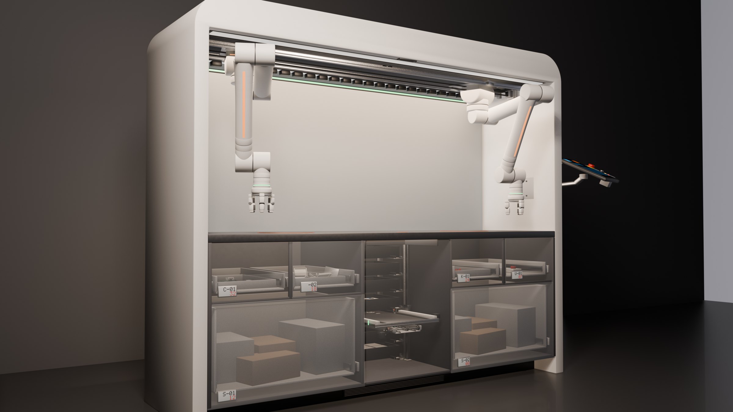
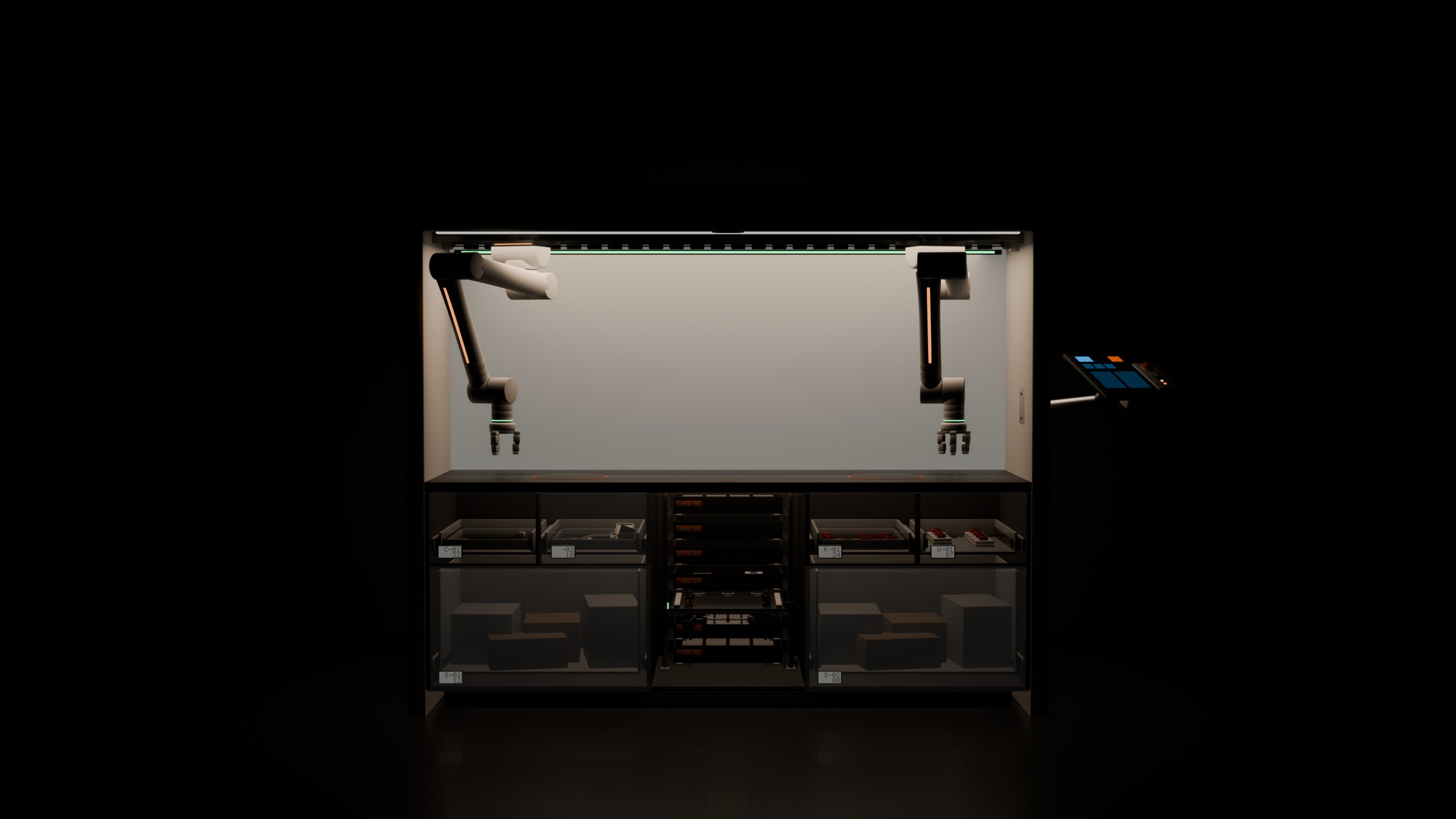
A compact robotic cell for a home desktop: two 6-axis arms on a shared rail, a central vertical lift, and automated storage. Everything here — the mechanics, kinematics, animation rig, and procedural sound — is generated entirely with Python in Blender.
I wanted to see what an automated assembly cell would look like if it were built for a home workshop rather than a factory floor. It had to be compact, quiet, and self-contained: pick parts from its own storage, assemble a small device on the desktop, and file it away into an output tray.
The design combines calm, clean enclosures with visible mechanics — exposed DIN socket heads, crossed-roller bearings, and warm tactile accents where mechanisms interact.
Two arms on a shared rail
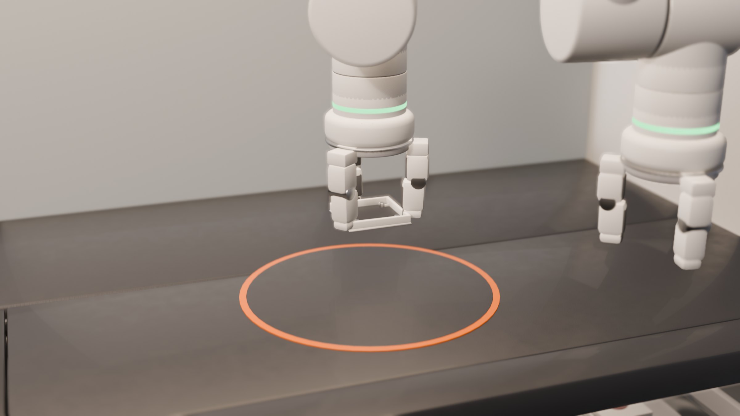
Both six-axis arms ride along a single linear rail across the back of the cell. Sharing the rail lets them divide the work naturally: one arm pulls raw components from storage and holds the fixture, while the other places circuit boards and presses enclosures together.
The kinematics are solved analytically for each joint, keeping arm paths smooth and repeatable without hunting or jitter.
Picking from loose storage
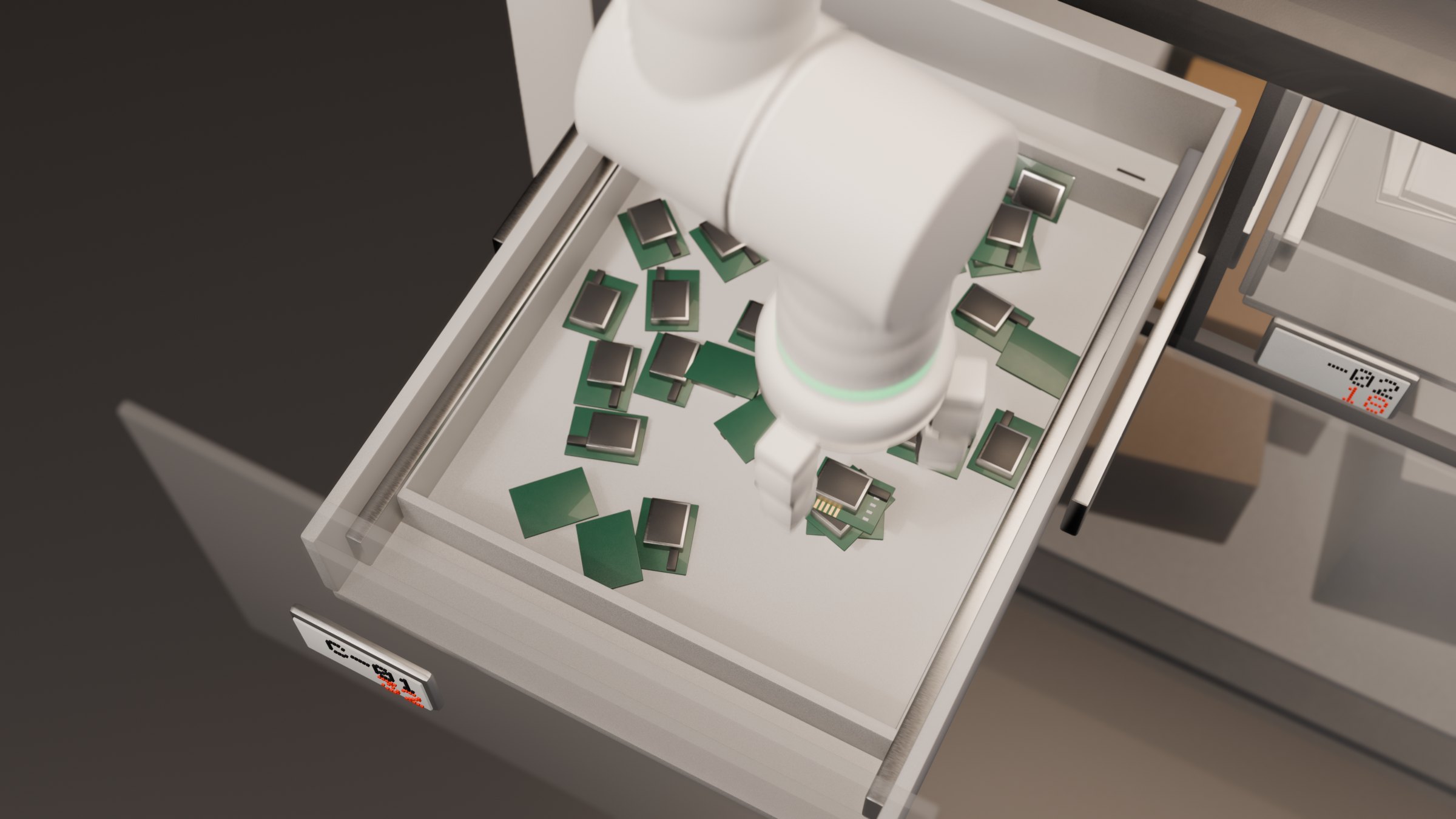
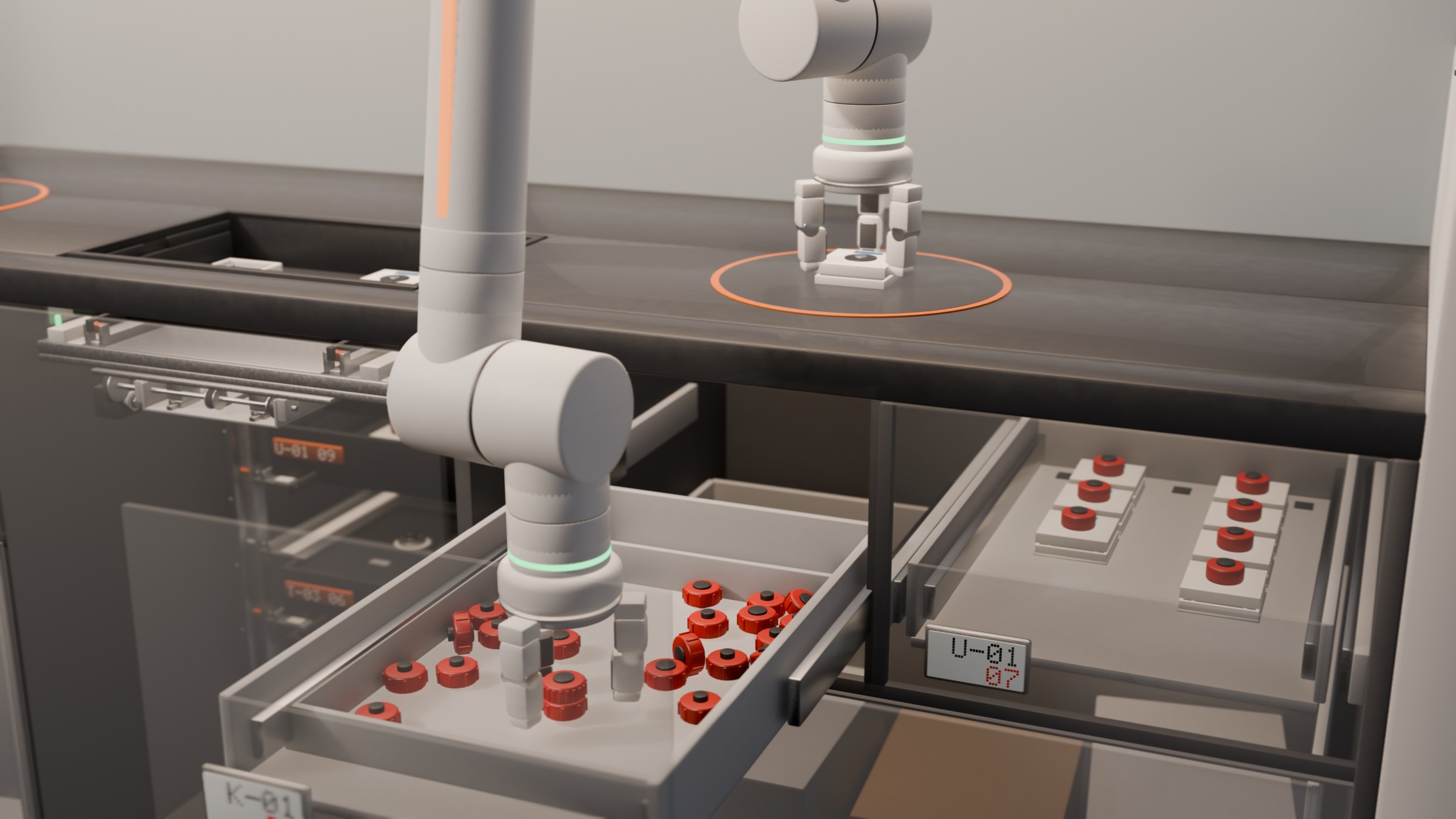
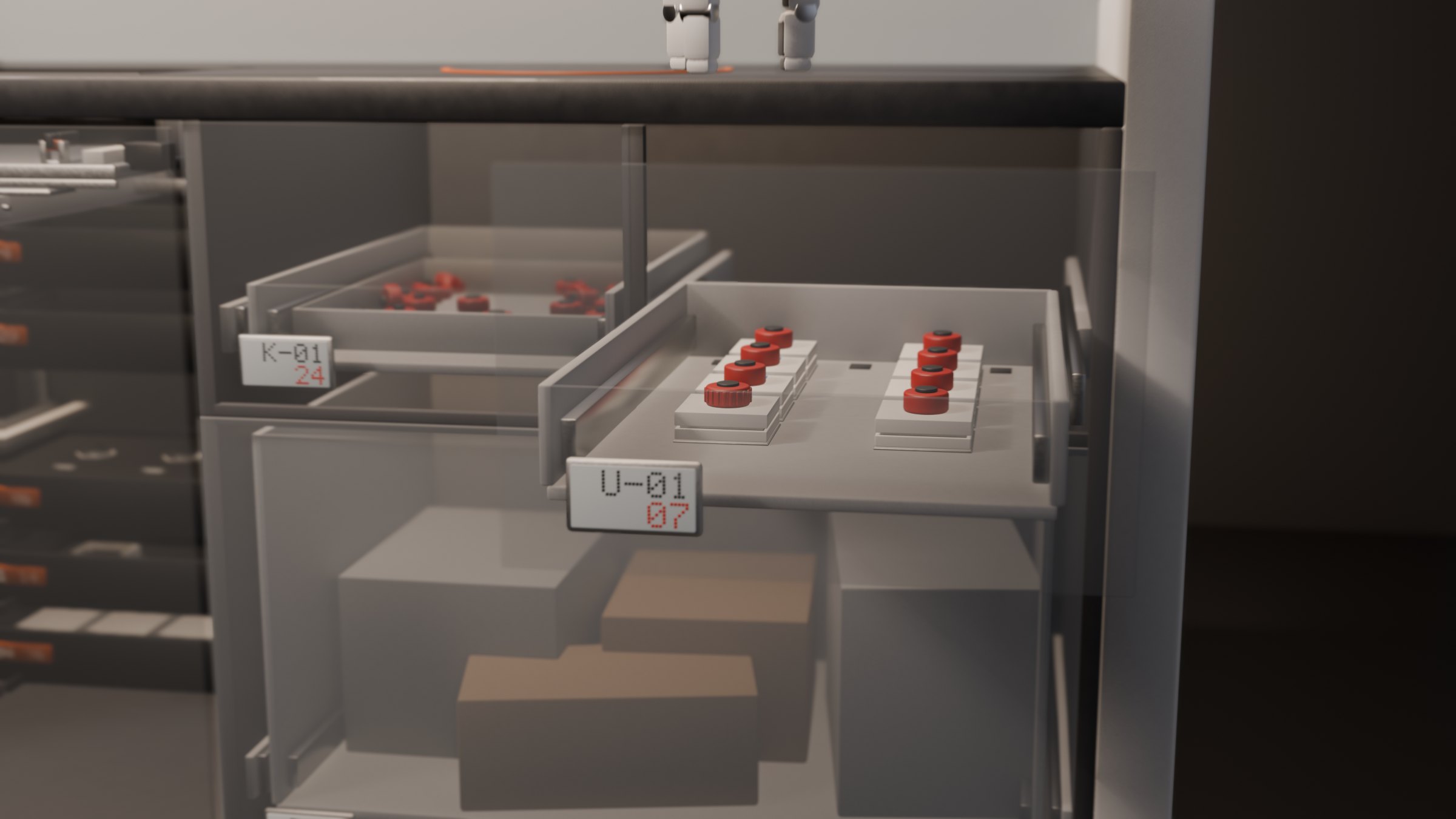
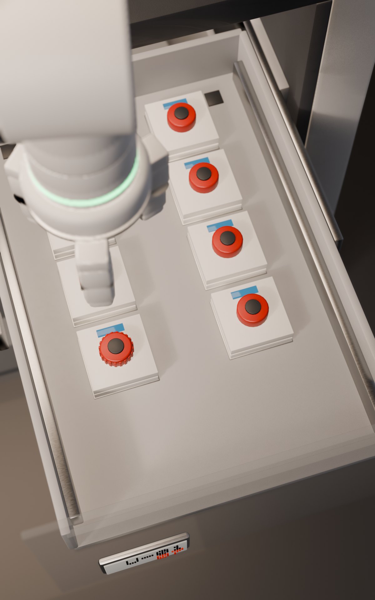
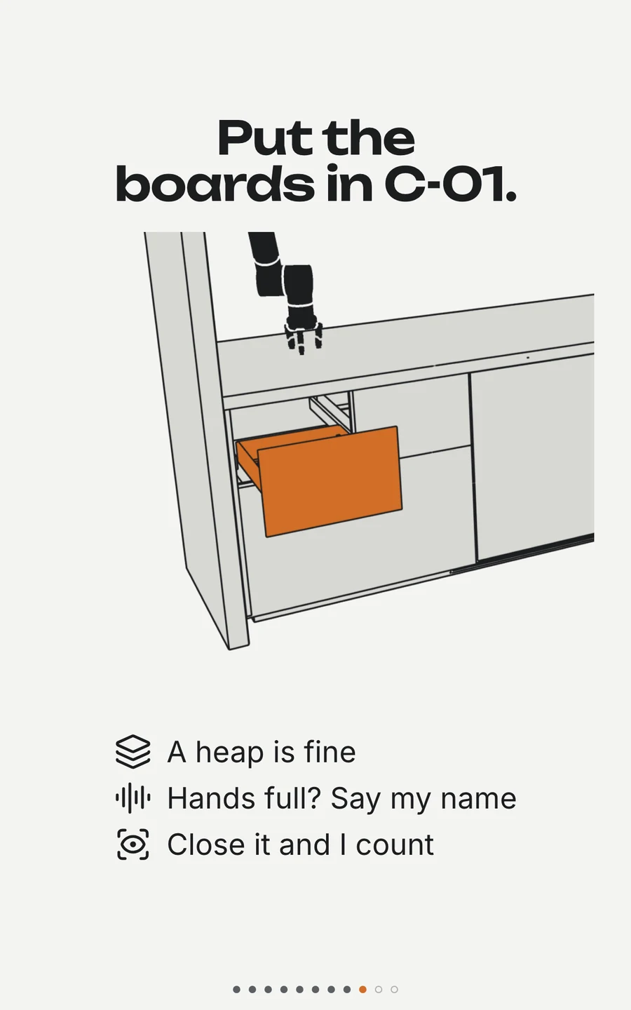
Under the work surface, three motorized drawers hold stock. In real small-batch assembly, parts rarely come in custom-molded trays, so these drawers store components loose in shallow bins — circuit modules, knurled dials, and housing halves in a jumble.
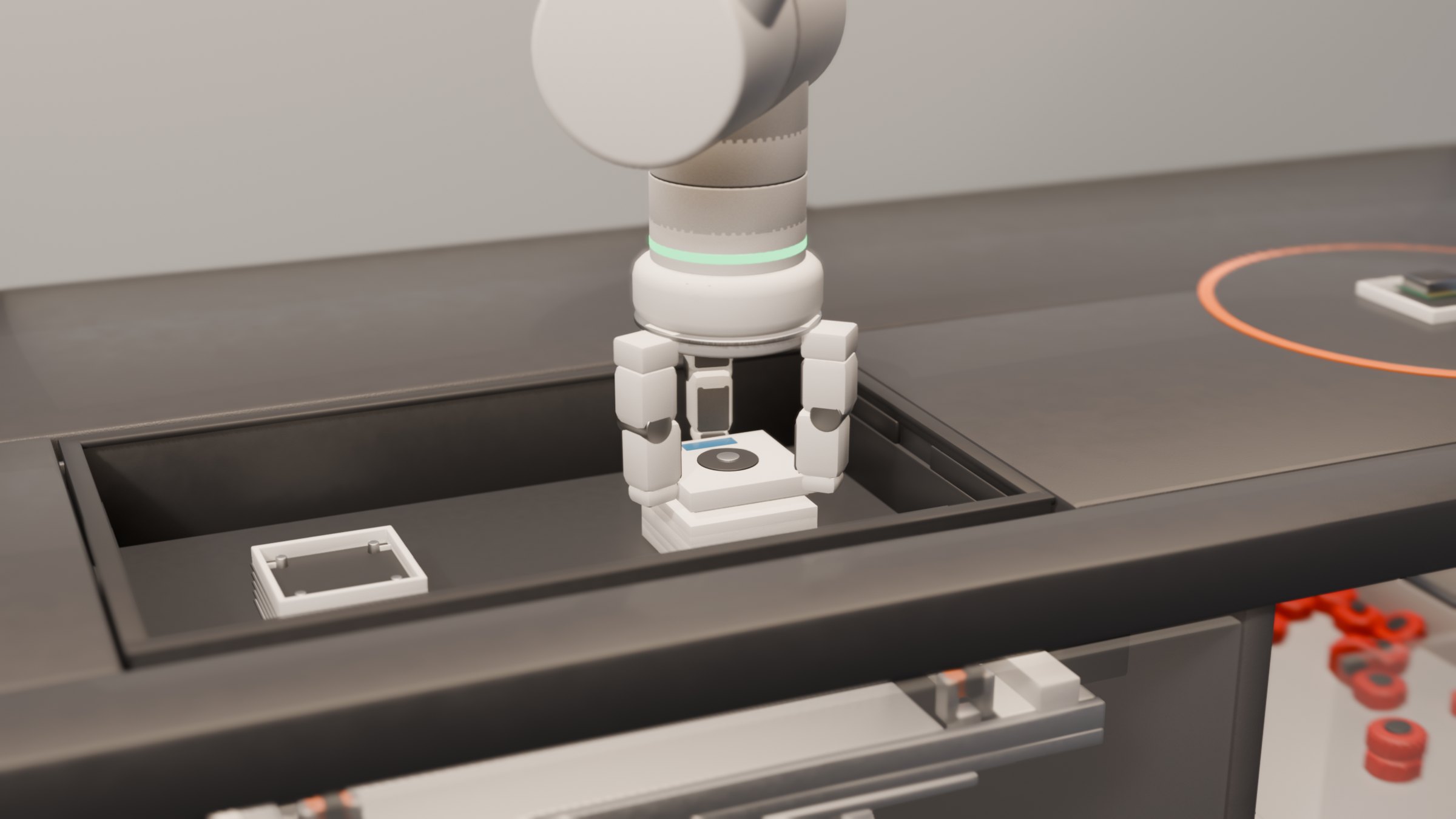
A wrist-mounted camera scans the bin, identifies the top piece in the pile, and rotates the gripper to match its orientation before picking it up.
The central lift mechanism
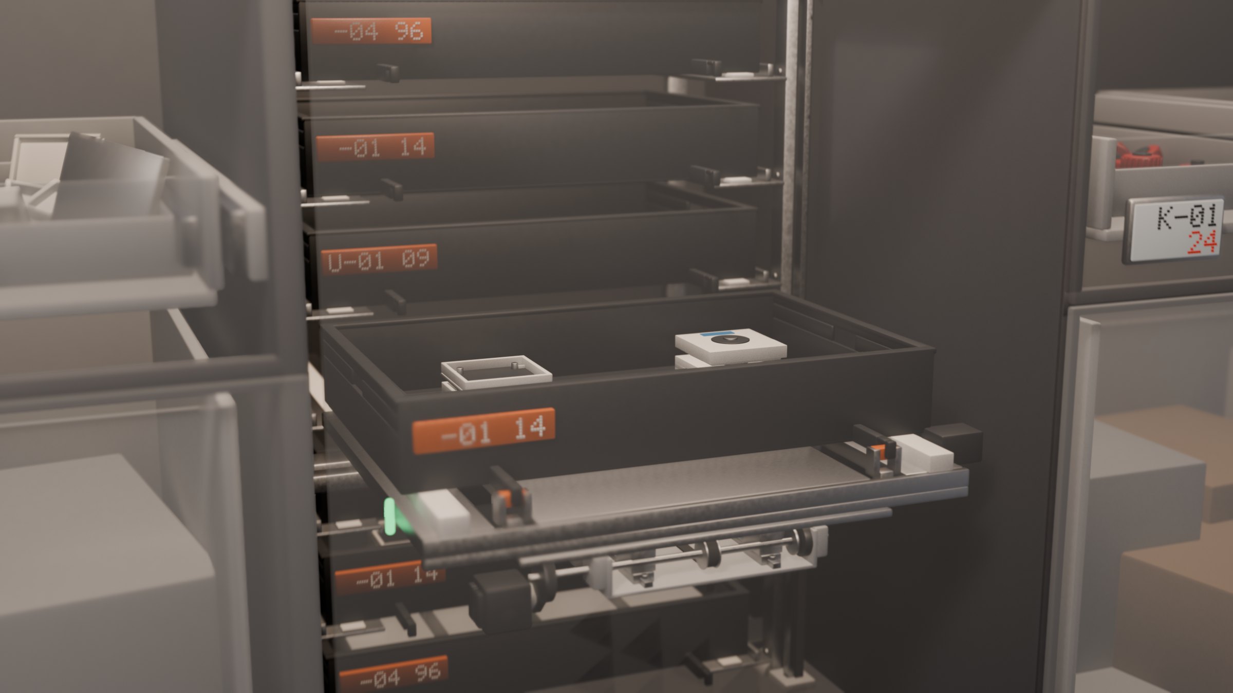
The centre tower is a vertical lift module holding seven component trays behind the fascia. In my first prototype, I tried pulling trays forward with a classic telescopic fork. It looked great, but in a compact 380 mm shaft it jammed immediately: a fork long enough to reach the rack had its tines stuck under the tray, unable to retract once delivered.
To solve this, I replaced the fork with a belt-driven shuttle running under the deck. Each tray has a notched tongue on the front face. Two pusher dogs pop up through deck slots, latch onto the tongue, and draw the tray forward. To release, the whole carriage simply drops 12 mm — letting the dogs slip out from the notch without needing a separate release actuator.
Assembling the controller

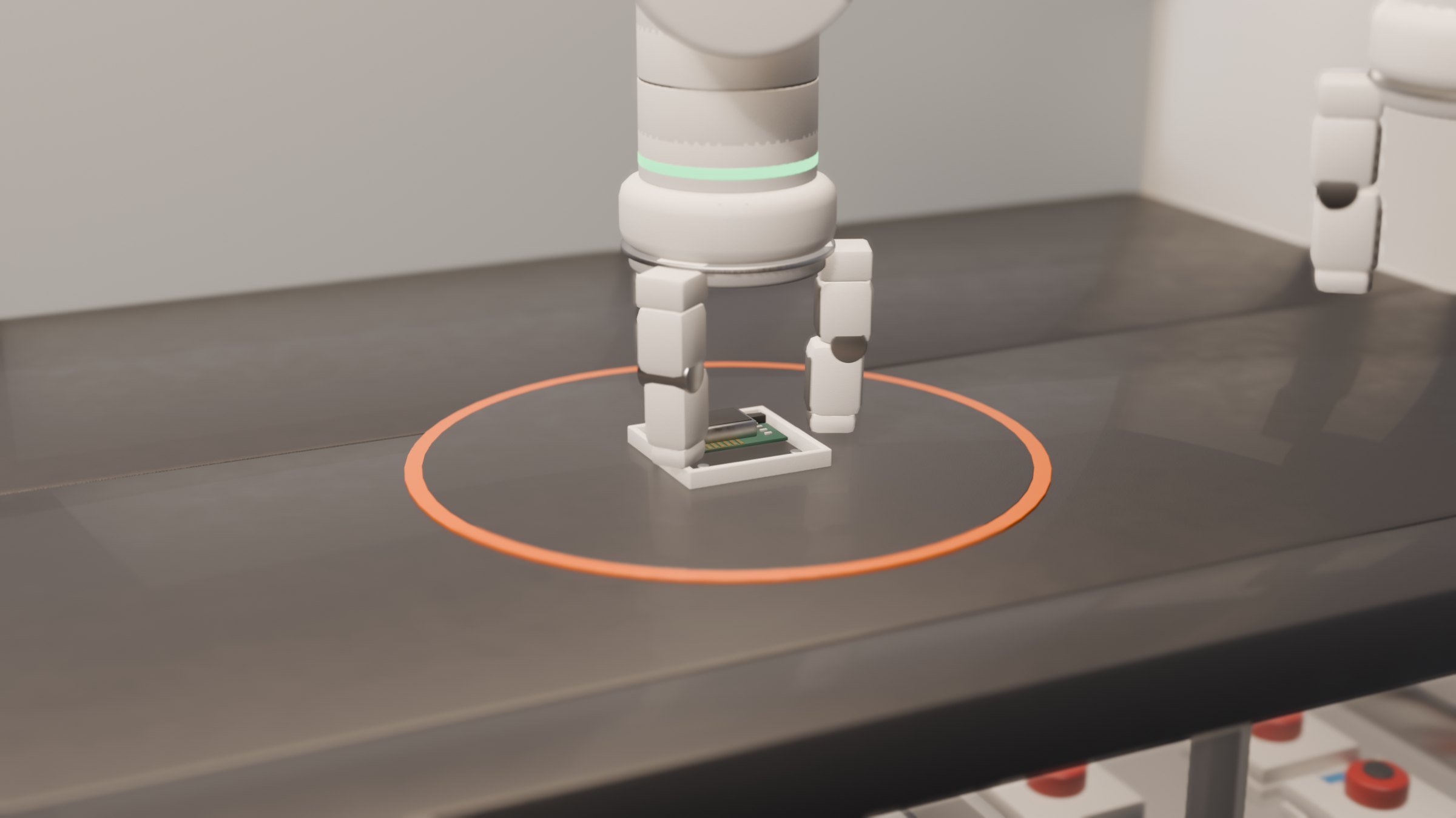
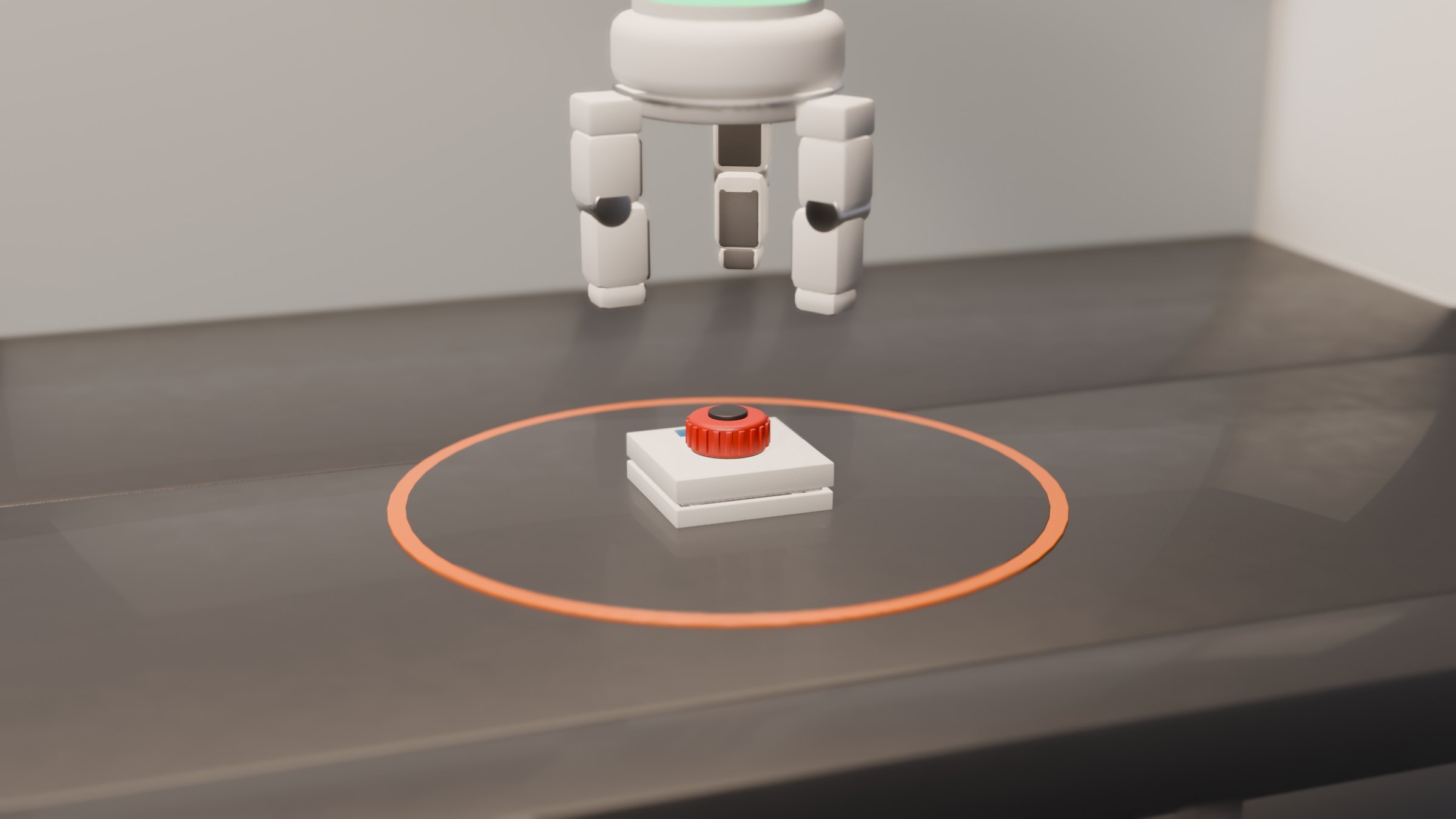
The cell builds a small handheld controller in four steps: the lift presents the bottom shell, the arm picks a circuit module from the drawer and seats it inside, the lift delivers the top lid to close the housing, and the second arm presses a knurled red dial onto the encoder shaft.
Once the enclosure clicks together, the arm picks up the completed device and files it neatly into the front output tray.
An e-ink status wall
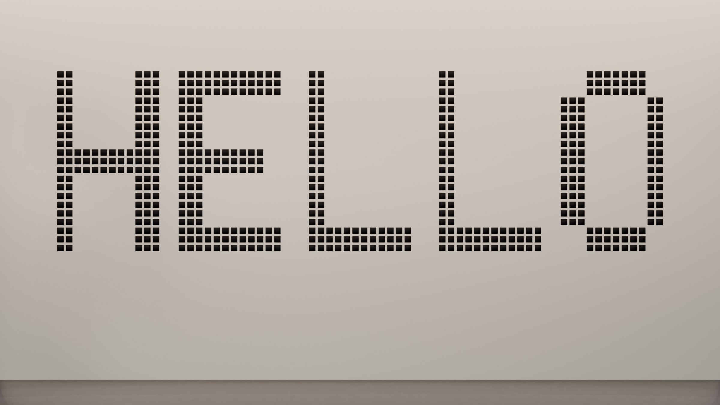
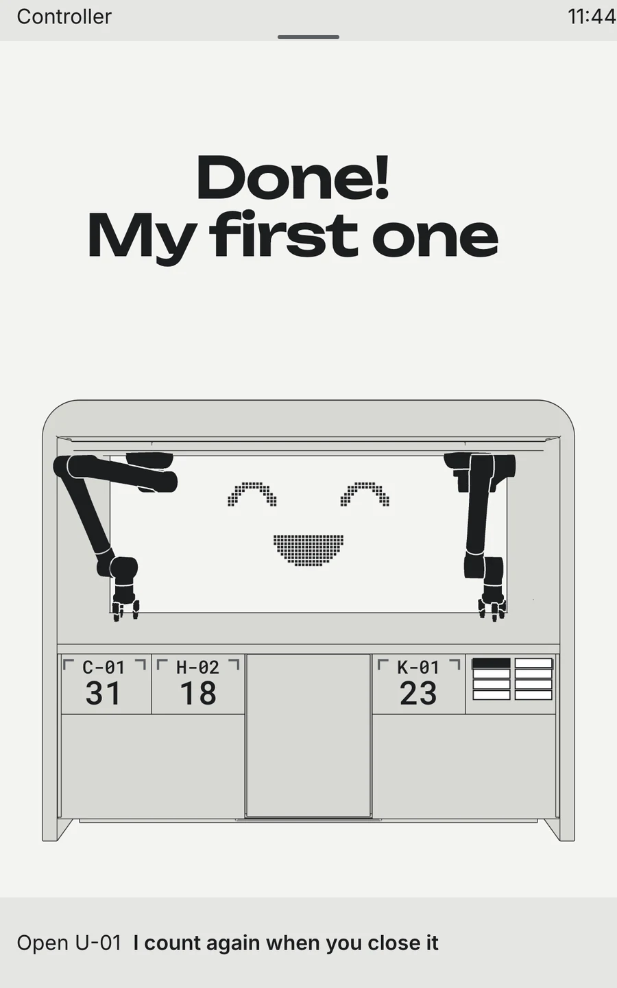
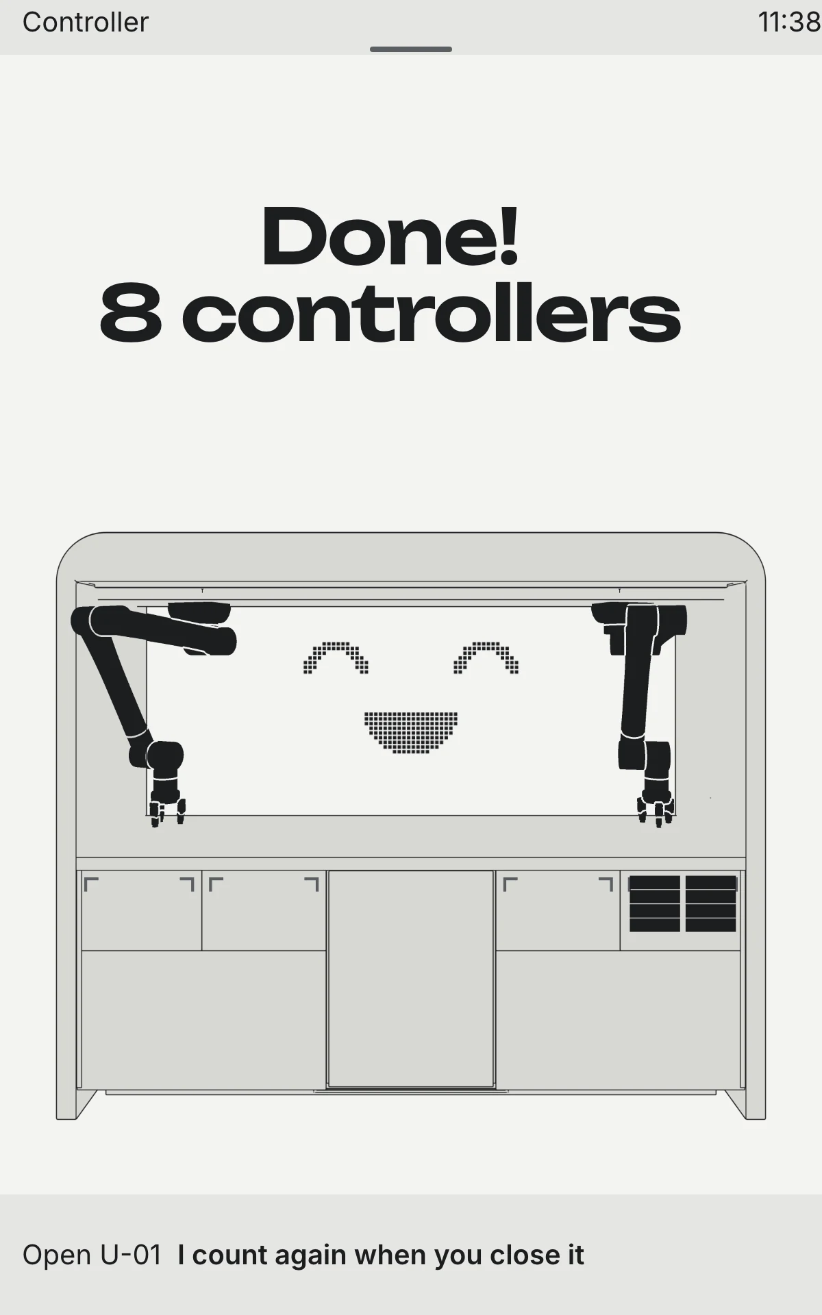
An e-ink dot-matrix panel is integrated directly into the cabinet's back wall. It stays dark while the arms are running — avoiding distracting animations while work is in progress — and lights up with a single «HELLO» only once the finished controller is safely stored away.
A screen that speaks human
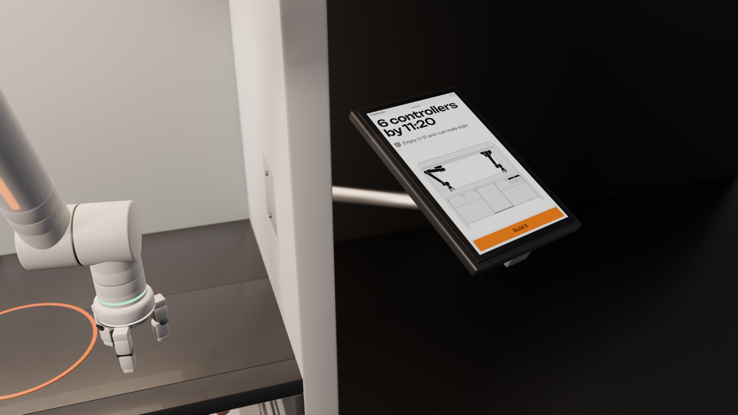
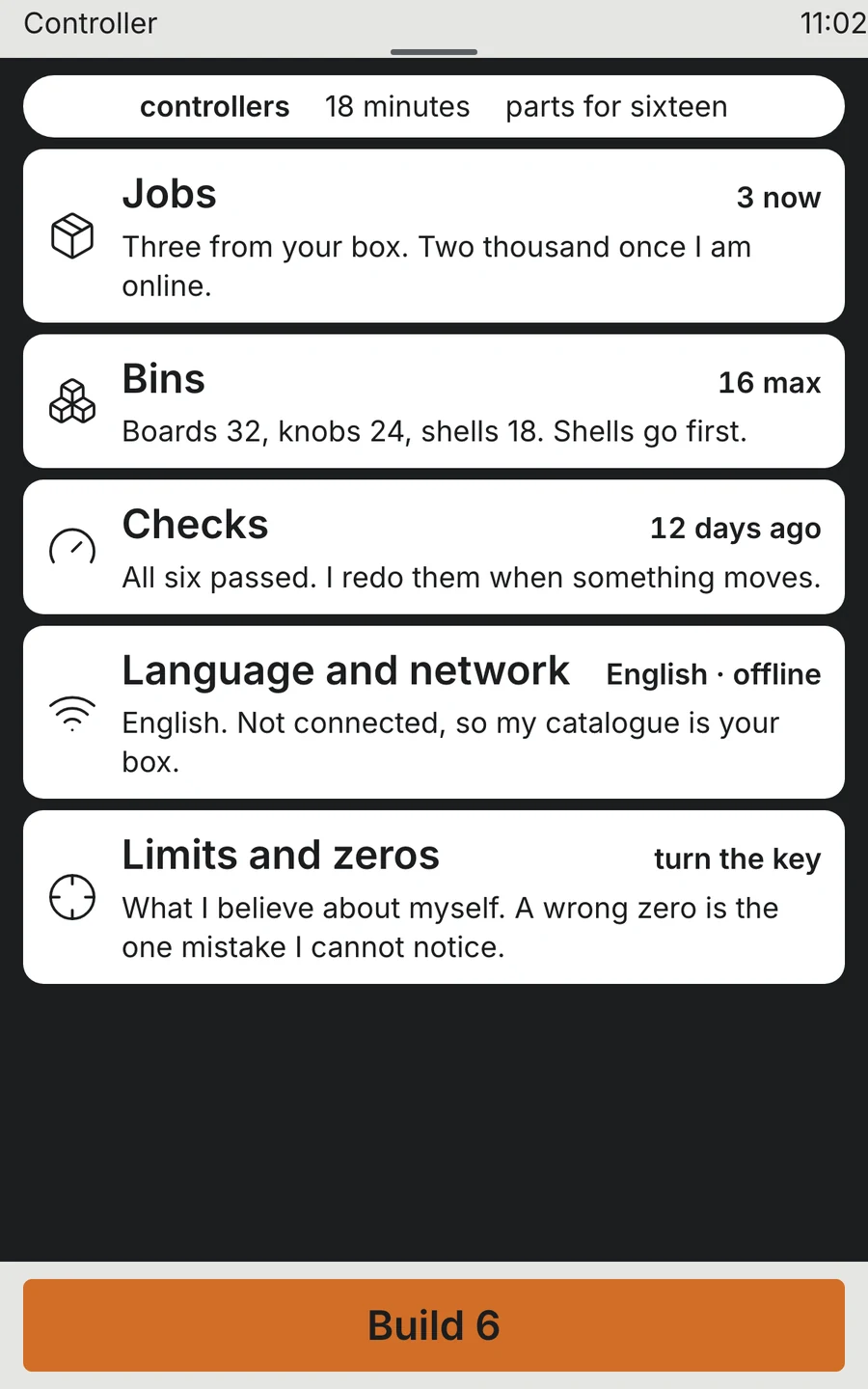
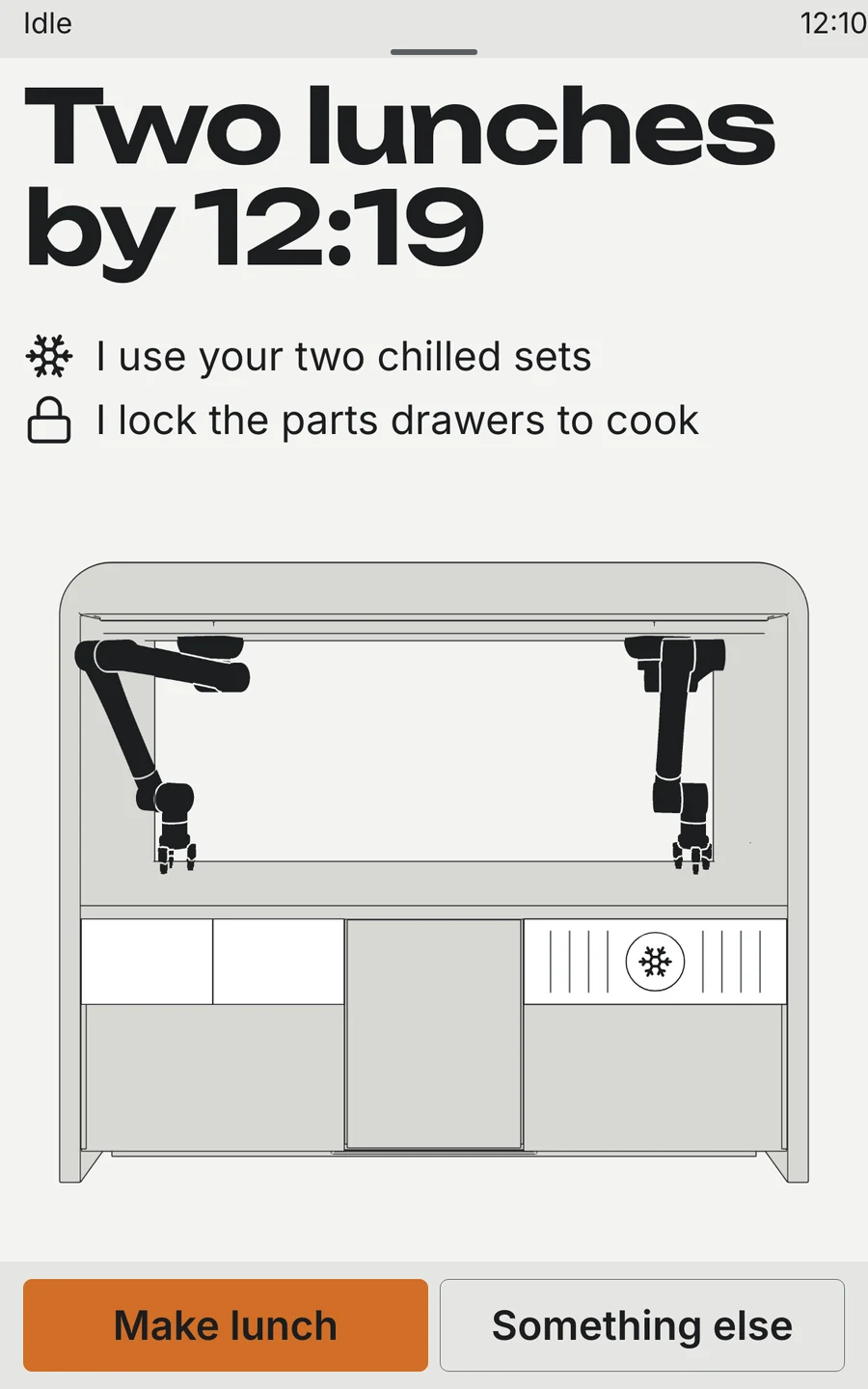
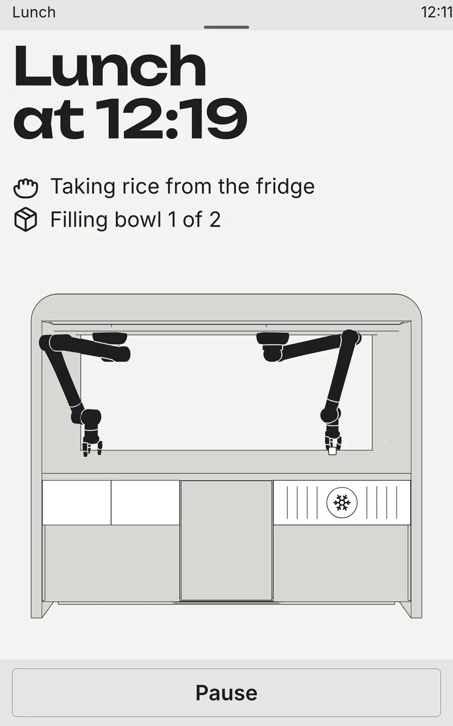
The cell needed a terminal, and every state it can be in needed a screen: waiting, counting, building, paused, stuck, done. My first drafts were full of state words — Free, Open, 11:38 — that meant something to me and nothing to someone standing at the worktop with a box of parts.
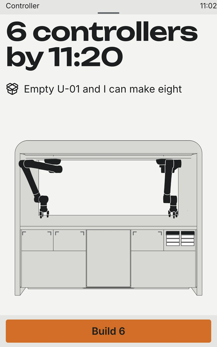
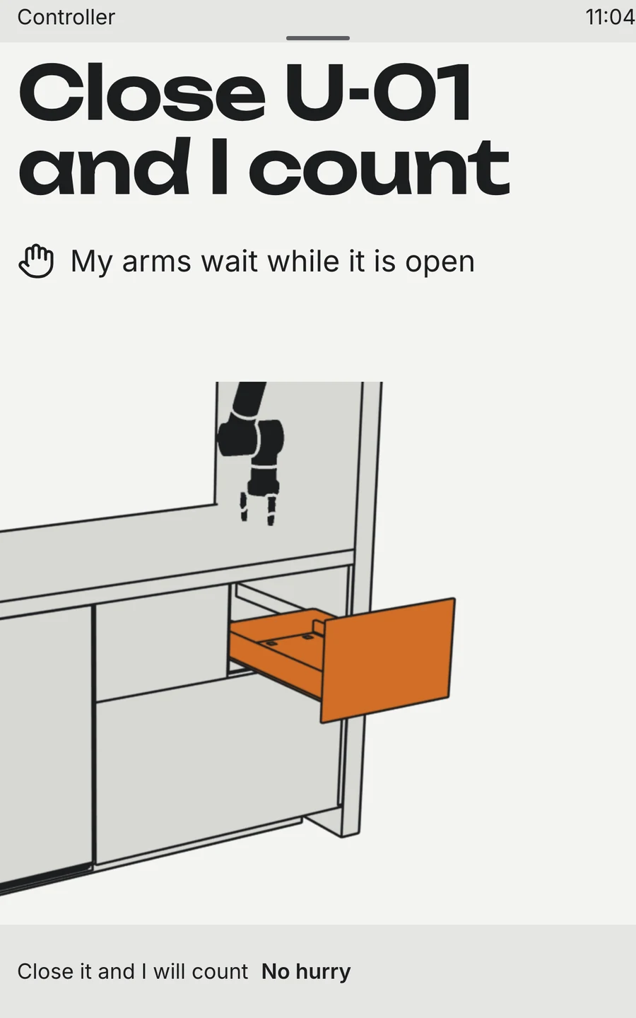
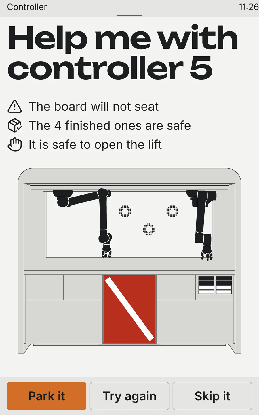
So every headline became either what you get or what to do next: 6 controllers by 11:20, Close U-01 and I count, Help me with controller 5. The details moved behind a pull-down shade, the way notifications live on a phone, and the rest of the screen went to a picture of the cell itself.
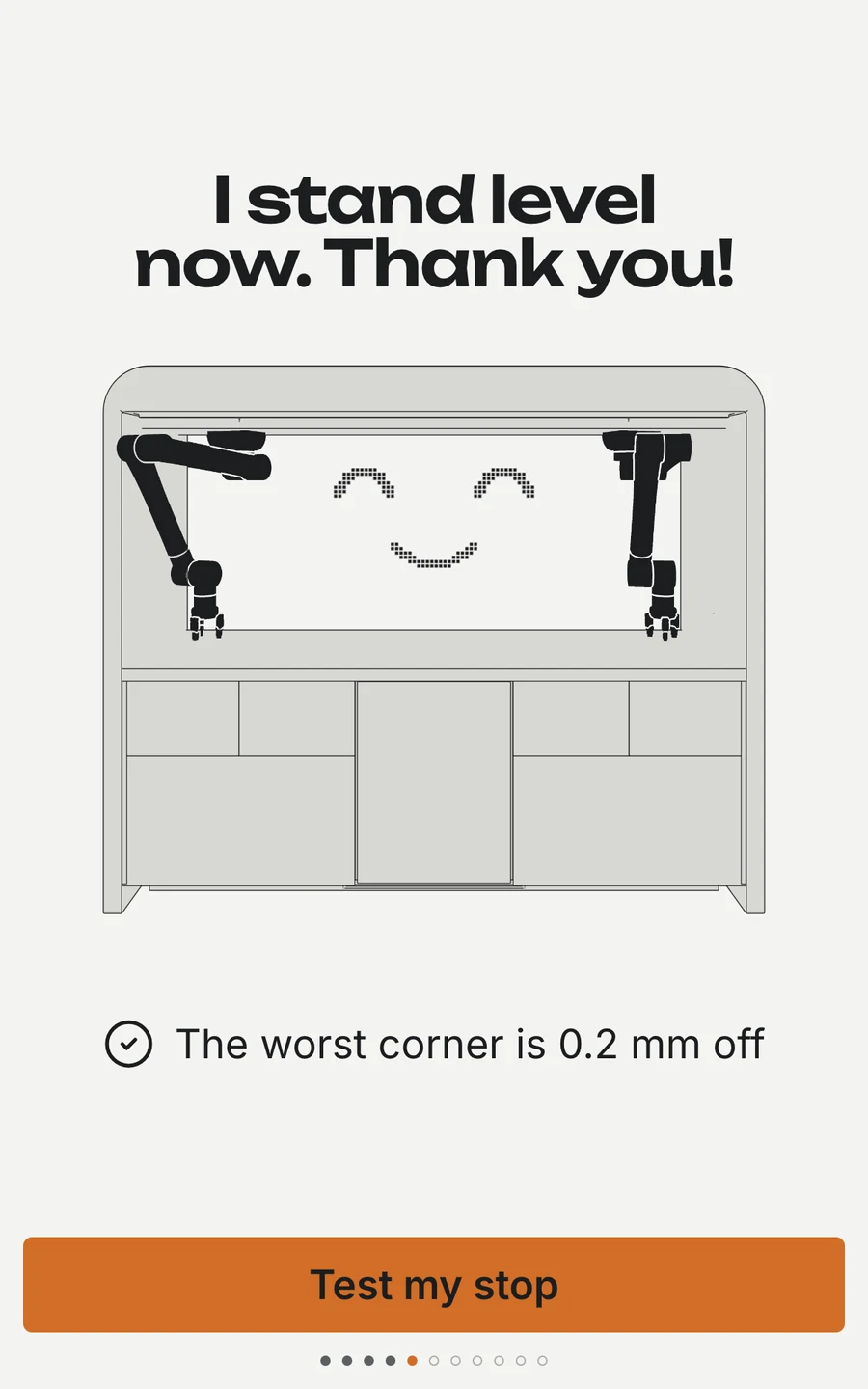
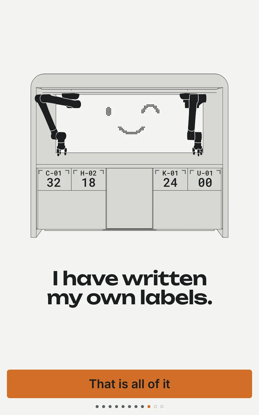
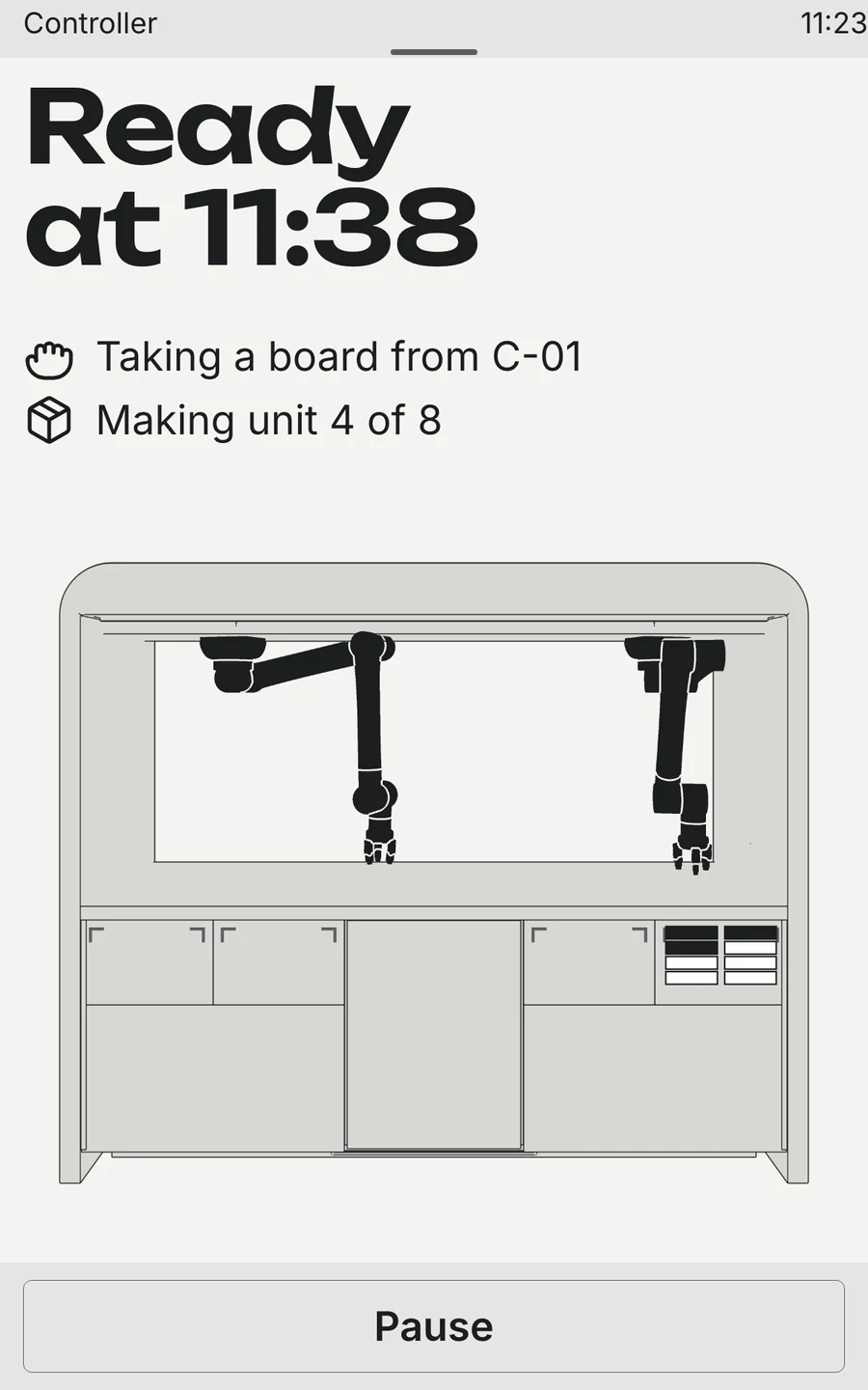
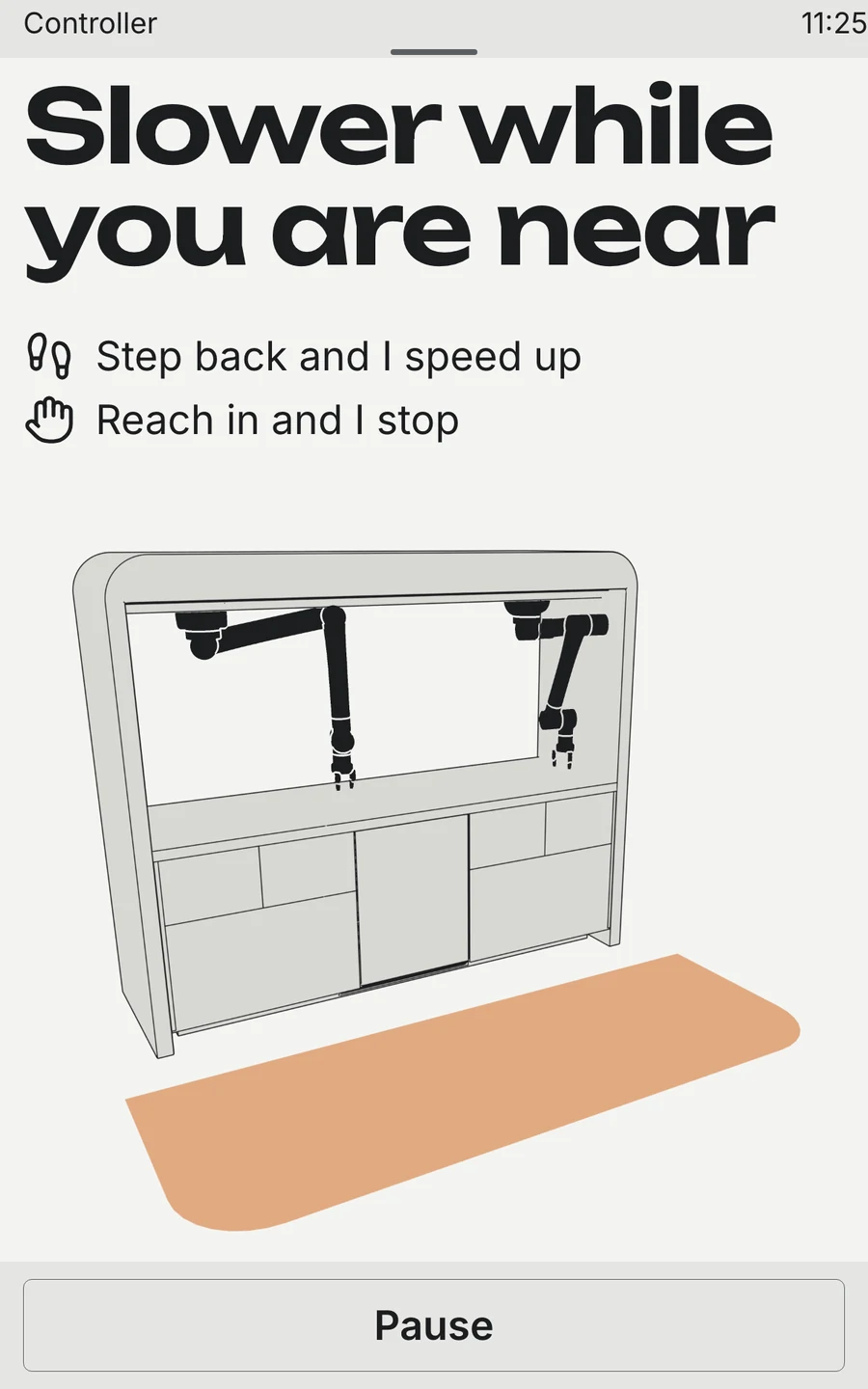
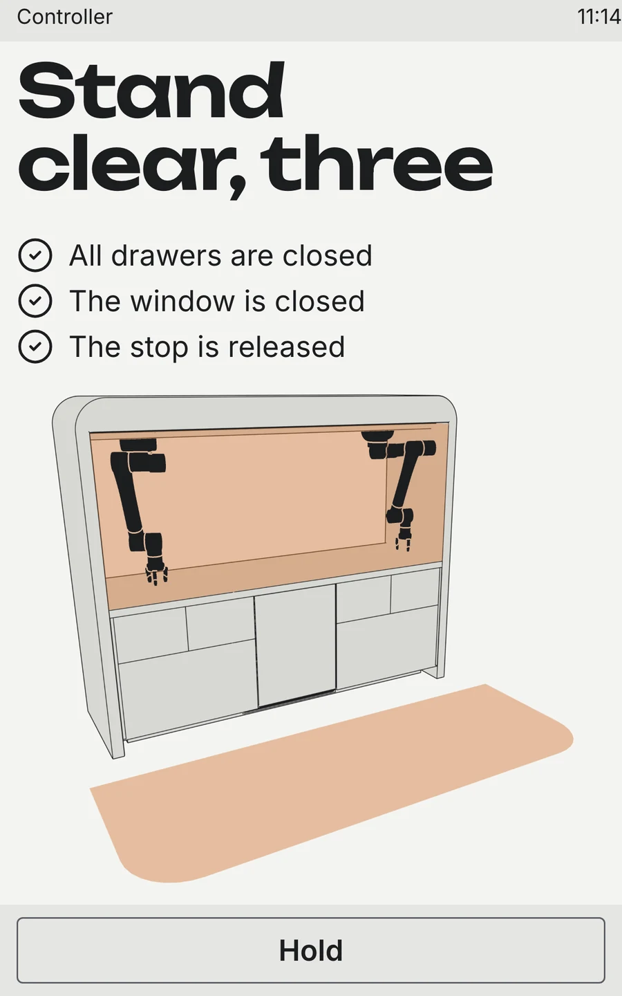
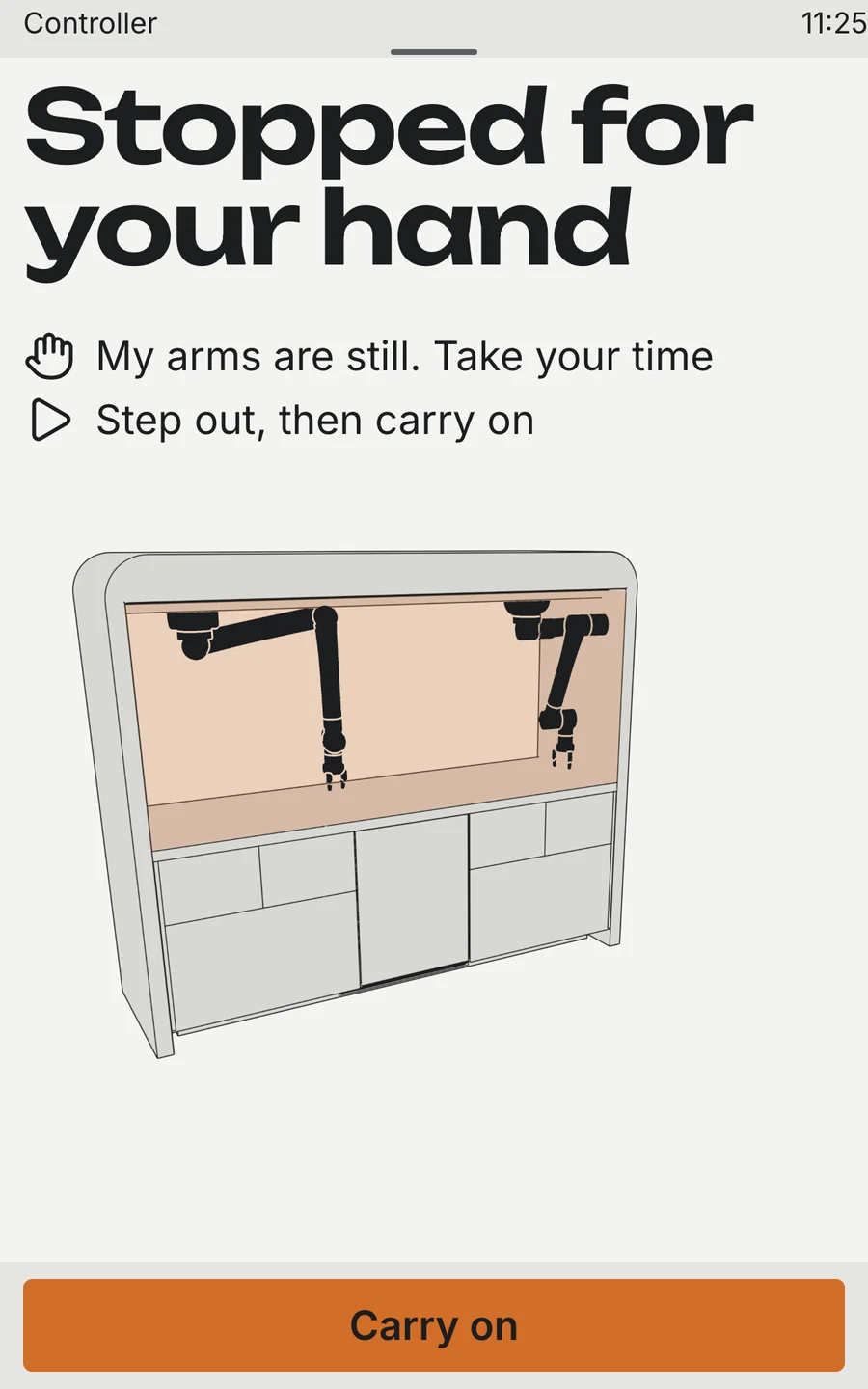
That picture is not a drawing. To keep the screens honest — and the language simple — I render them from the same 3D model as the film: a front view, a three-quarter view, the arms as separate layers. The state goes on top in a thin layer of its own: the drawer you need, the zone you are standing in, the lift that jammed. The screen cannot show a drawer the machine does not have, and when a batch is done the e-ink back wall draws a smile in its own dots.
Onboarding, from Wi‑Fi to the first part
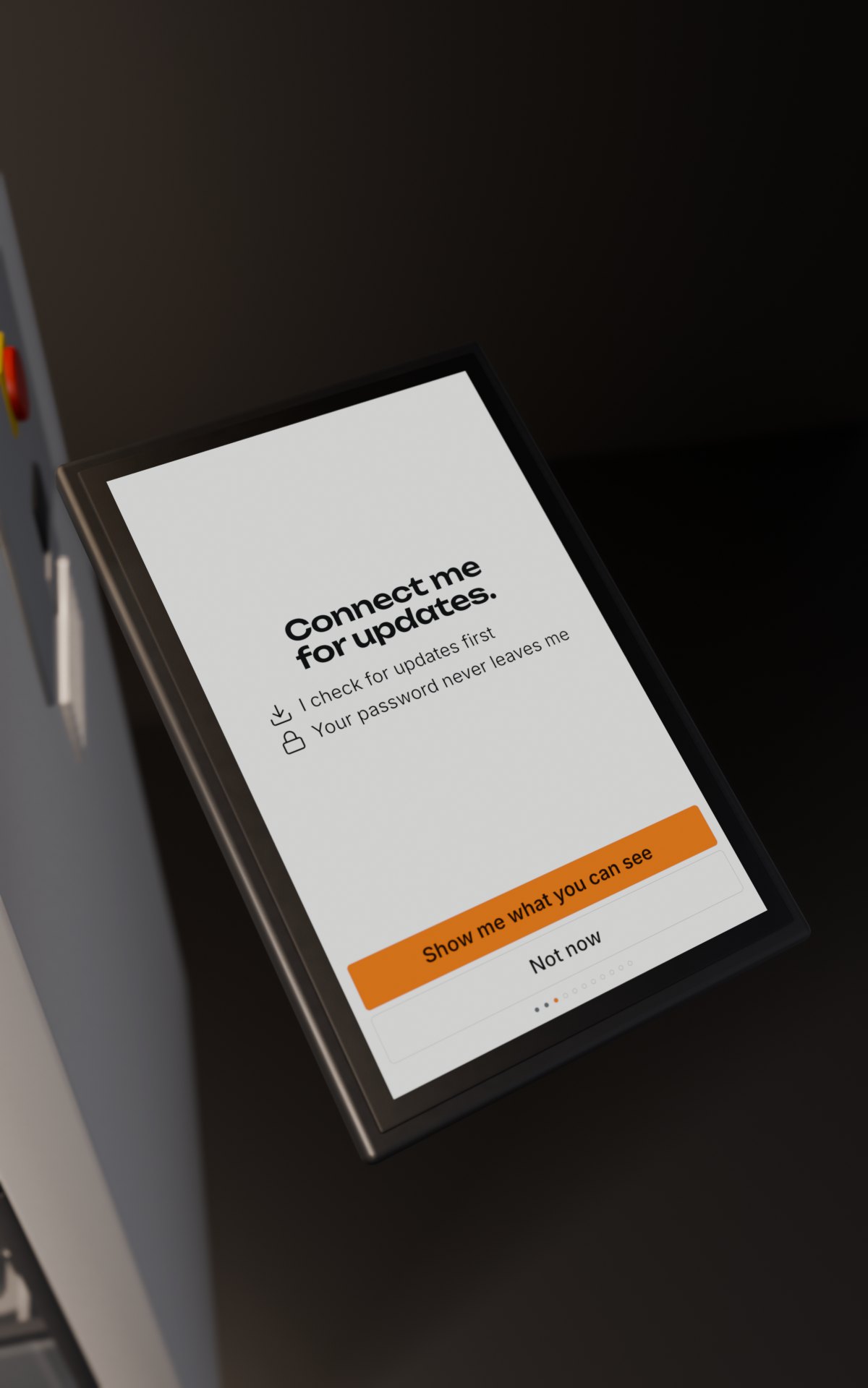
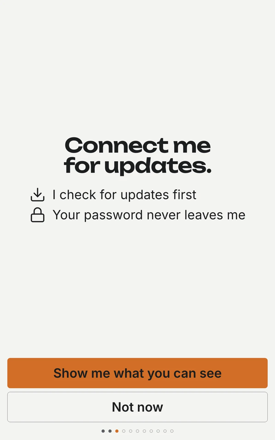
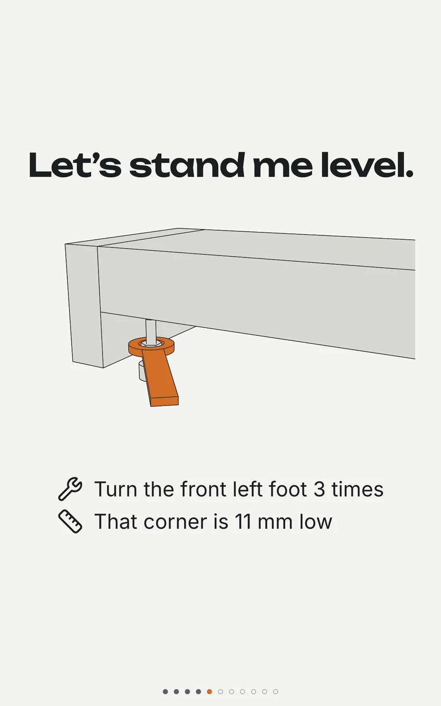
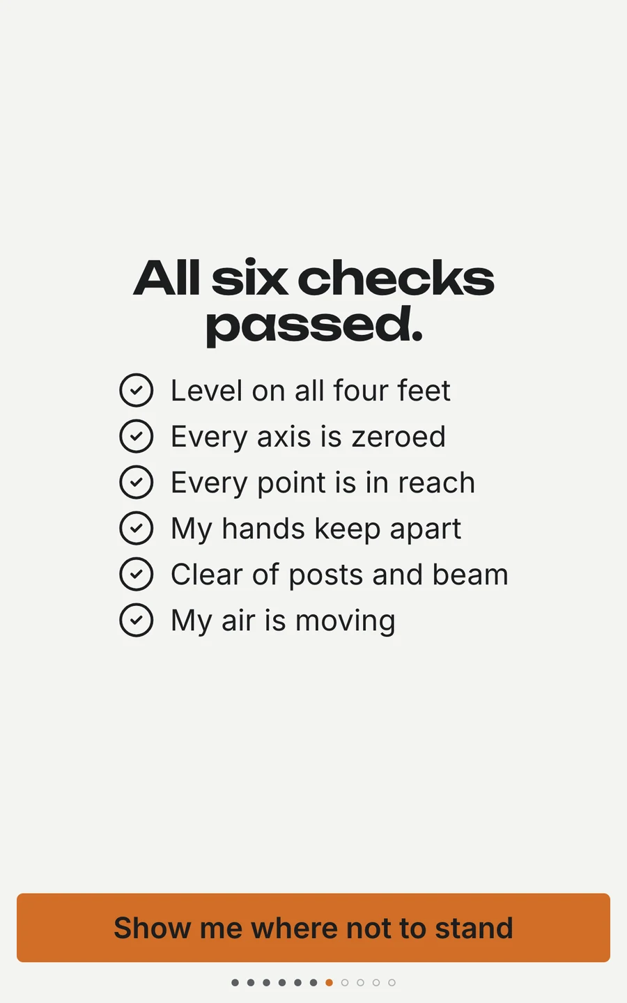
The 3D layers paid off most in onboarding, where someone who has never met a robot sets one up alone. It starts with Wi‑Fi, so the cell runs the current firmware before anything moves. Then comes levelling — the cell measures its own floor and names the foot to turn — followed by calibration and a round of self-checks, each a number the cell measured rather than a question it asks.
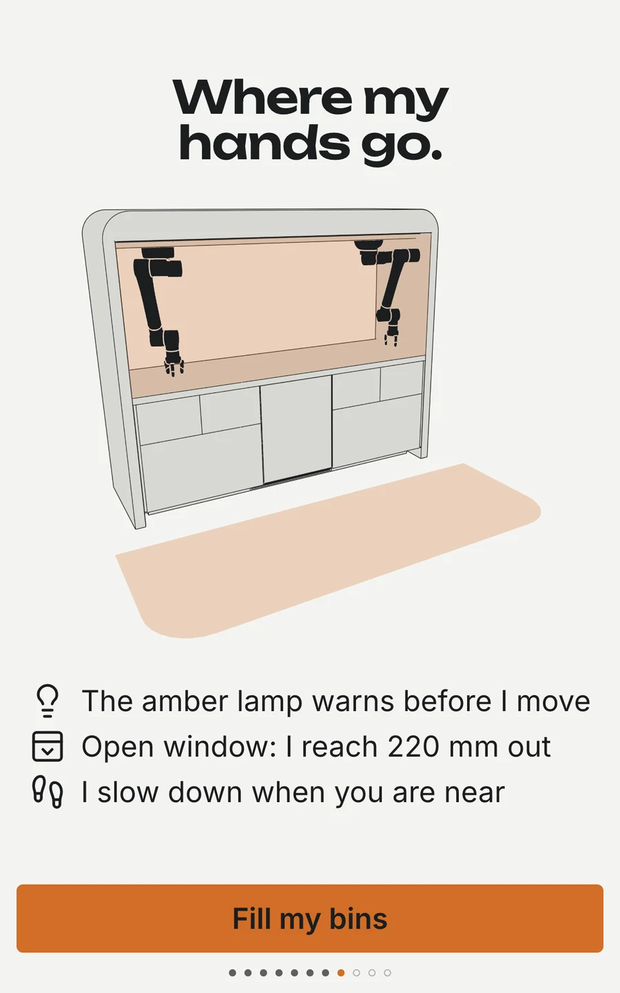
Only then does it show where its hands will reach, ask for parts one drawer at a time, and build its first controller while you watch.
Connect and levelsteps 1–4
Meet the stop, and the limitssteps 5–8

Parts, and the first buildsteps 9–12
Then, every day
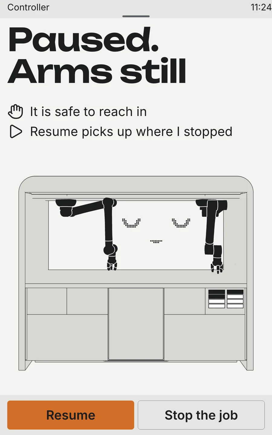
Once it is set up, every screen is built the same way: a headline that says what you get or what to do, a line or two of why, the cell itself with only the thing that matters lit, and one button. Step closer and the arms slow down; reach in and they stop; if a part jams, the screen names the part and says whether it is safe to open the lift.
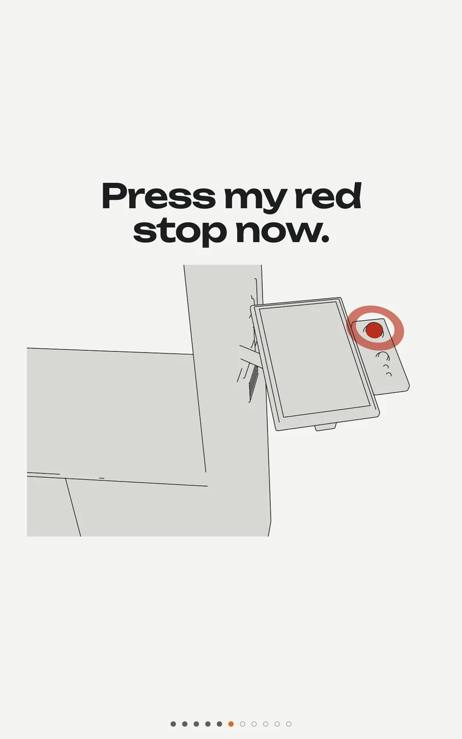
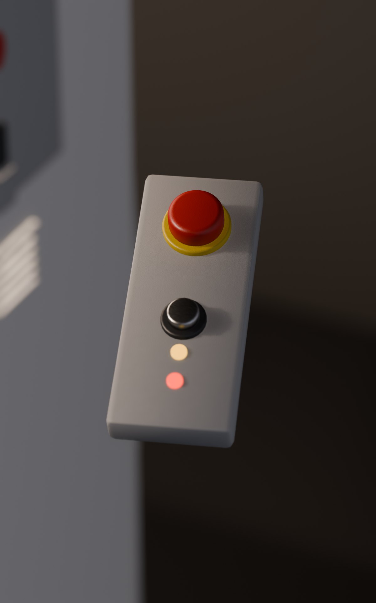
The red stop is not one of the screens: it is hardware, on the console beside the terminal, and onboarding has you press it with your own hand before the first real move.
Making thingsready, building, done
Around peoplethe zones, and what happens when you come close
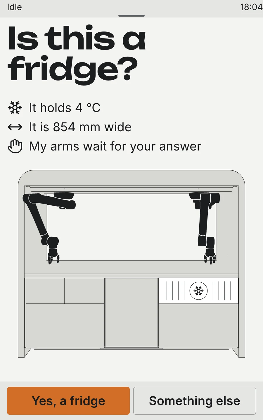
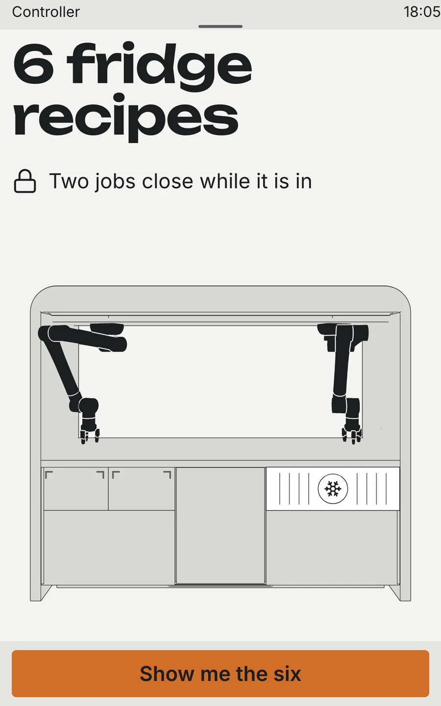
A new modulea fridge in the right bays
Generated entirely with Python
Every element in this scene was generated procedurally with Python in Blender. Every bracket, bearing housing, and cable gland is defined mathematically with real millimetre dimensions. Parametric properties drive the entire animation rig — from arm kinematics to drawer slides.
Even the soundtrack is synthesised directly from the animation: the script reads joint rotational speeds frame by frame to drive physical audio models, creating authentic servo whines, gear hums, and mechanism clicks without audio samples.
More projects